Looking for some help understanding the E-motors

Mitsubishi Outlander PHEV Forum

Help Support Mitsubishi Outlander PHEV Forum:

This site may earn a commission from merchant affiliate links, including eBay, Amazon, and others.

anko

Well-known member
Joined
Dec 1, 2014
Messages
3,405
Location
Netherlands, Utrecht area
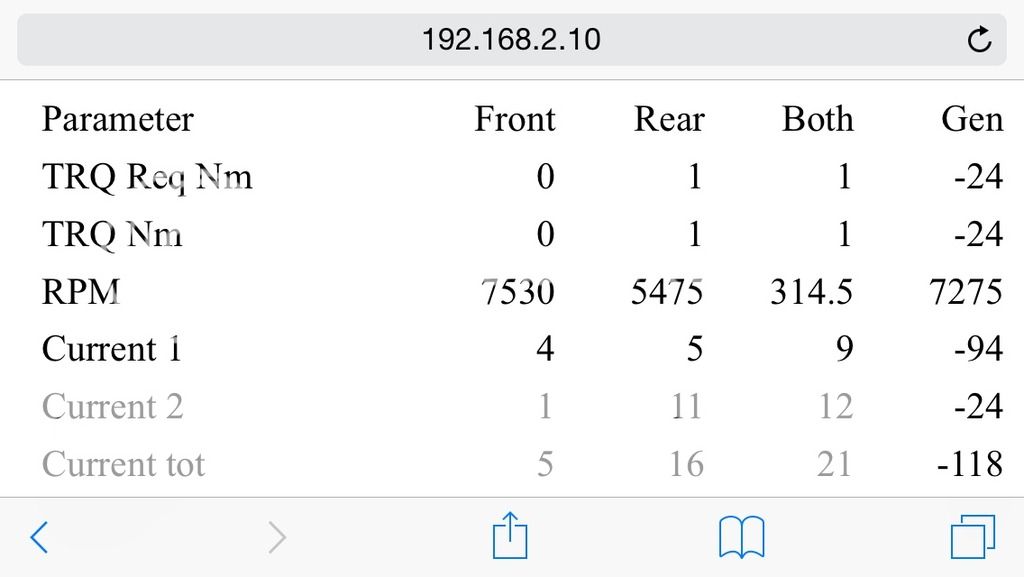
As part of my OBDII adventure, I am trying to create a dashboard showing the behaviour of the E-motors. What I have so far is this:

IMG_3260_zps9cmt3p7b.jpg


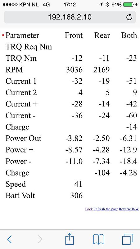
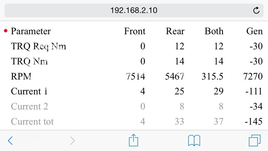
First column is obviously the name of the parameter. Second column is value for front motor, third is rear motor, and fourth is second and third column added together.

Rows are:

- TRQ Req Nm: Torque in Nm Request(ed by ECU?), I disabled this for the time being, as this parameter requires one extra separate OBDII request per motor, which makes sweep time to long.
- TRQ Nm: Torque delivered
- RPM: spinning speed
- Current 1: Is a parameter in the motor ECU that expresses current in Amps
- Current 2: Is a second parameter in the motor ECU that expresses current in Amps
- Current +: Me trying to add current 1 and current 2, trying to see if I could match battery output.
- Current -: Me trying to subtract current 2 from current 1, trying to see if I could match battery output.
- Charge: Fourth column shows battery output in Amps.
- Power Out: Torque in Nm * RPM / 9.5488 / 1000 to yield kW
- Power+: Attempt to determine power consumed by E-motor via (Current 1 + Current 2) * battery total voltage
- Power-: Attempt to determine power consumed by E-motor via (Current 1 - Current 2) * battery total voltage
- Charge: Fourth column is kW output from battery, third column is Wh output from battery per km
- Speed: speed in km/h
- Batt Volt: battery total voltage

Most numbers are negative, because I took the photo during regen breaking. Doesn't really matter.

What I try to do is match power output from the battery to power consumption by the E-motors (this is all in EV mode).
Also, I try to compare power consumption by E-motors to power output by E-motors.

- need to finish this post later, as the family needs me -
 
Hi Anko

I think you need some positive values for the e motors so that you can work out the correct parameters against the max known revs of the motors with the reduction gears factored in. Then the test needs to be repeated at various speeds to see if you come close to the profiles in the technical docs. It's really difficult to start with regen figures because it depends on the regen level selected and there are no published figures/graphs of regen power output to my knowledge. Great work though - keep on going. :D
 
Well, I am quite certain about the base parameters themselves, as I have compared them to readings made by a commercially available device. So, RPM, Torque, Amps and such will be correct. Even though this particular screenshot was taken during breaking.

It is just that I would like to figure out how to interpret these figures.

For example, I would like to compare E-motor output to E-motor power power input, in order to establish motor efficiency. Or compare E-motor power input to battery and / or generator power output to see if power was going somewhere else than to the motors. And so on.

How the determine the output, I am rather certain about (torques * rpm / some factor). I get rather reasonable values.
For the input power however, I have to currents, current 1 and current 2, per motor. I thought I add these up and multiply by voltage of the HV battery to get power input. It seems however, if I subtract current 2 from current 1 and multiply by voltage, I get much closer to battery output. I have no idea how that works. What could current 1 and current 2 mean?

Also, I have checked what happened when I pressed the gas pedal with the handbreak on. I saw a huge input current. Way higher than the current output of the battery. Could it be that the battery voltage is not the correct value to use when converting motor input current to motor input power?

Parameters that should be available per motor are:

01.Motor torque request
02.PHEV-ECU run mode
03.Ready condition(PHEV)
04.Condenser discharge request
05.MCU shutdown request
06.PHEV-MCU communication lost
07.MCU CAN fail
08.Motor/Inverter coolant TEMP
10.Water pump fail flag
11.DTC detectable flag
12.Water pump revolution speed
13.Motor torque
14.Motor speed
15.Condenser voltage
...
19.IGBT overheating state
20.Current DTC
21.Condenser discharge
22.Ready condition(MCU)
23.IGCT voltage keep request
24.HW gate
25.HW shutdown
26.Motor coil maximum temperature
27.IGBT maximum temperature
28.CPU temperature
29.IGBT estimated temperature
30.Condenser temperature
31.Motor Oil Temp
...
34.Motor current
35.Motor current2
36.Motor current(target:dif)
37.Motor current2(target:dif)
38.IGBT1 temperature
39.IGBT2 temperature
40.Coil temperature(U)
41.Coil temperature(W)
42.Req.coolant water flow quantity
43.CPU operation time
44.MCU soft version
45.IGBT3 temperautre

Any idea what "Motor current(target:dif)" could be? Or "Condenser voltage"?
 
Anko
I would think that the control systems would be supplying AC to the motors either pulsed or voltage controlled.
Surely its not a straight function amps x battery voltage.

This course seems to imply that converting the power from AC to DC and then back again is quite a specialist subject.

http://training.sae.org/seminars/c1045/

But keep up your investigations, I am finding them extremely interesting.
Sort of reverse engineering.
 
The condenser voltage is the voltage on the main capacitor bank. The H-bridge E-motor controller is most likely where it is located. The battery and main wiring loom has a finite internal resistance, and the condenser absorbs and sources high peak current transients, to prevent damage to the switching components when the battery is unable to sink or source the peak energy demands.

We will all have differing opinions re important aspects of the PHEV's available data. I think that we need to separate relatively static data, like coolant temperature and battery voltages from the really dynamic data like torque and current and speed and rpm etc. We are stuck with the efficiency of the motors as supplied. I am all for data that may help a driver find ways to make best use of the equipment in the PHEV.

We are lacking displays of generator power, and battery power and only have E-motor power and petrol consumption. We have a hybrid power source without tools to make best use of the combinations. EV only or ICE only are available, but we would need what the battery is doing in combination with the ICE and E-motors.

My last encounter with a steep hill at low speed highlighted a need for instrumentation, like torques on each motor to be available.
 
gwatpe said:
The condenser voltage is the voltage on the main capacitor bank. The H-bridge E-motor controller is most likely where it is located. The battery and main wiring loom has a finite internal resistance, and the condenser absorbs and sources high peak current transients, to prevent damage to the switching components when the battery is unable to sink or source the peak energy demands.
Thanks for trying. But I have NO idea what you are talking about. For now, I will try to multiply current 1 and current 2 with condensor voltage and see if that kind of matches battery power output.

gwatpe said:
We will all have differing opinions re important aspects of the PHEV's available data. I think that we need ....
Sure. This is why I created a separate topic for this ;) This was not necessarily meant as input for the app that is being worked on. Although, ideally such an app would be configurable .... A boy can dream, can he?

gwatpe said:
We are stuck with the efficiency of the motors as supplied.
Doesn't mean it wouldn't be nice to somehow visualise or demonstrate it. Especially, I would like to be able to understand what happens at very low speeds by interpreting the appropriate parameters: why does my engine start when towing my caravan out of a ditch, while at that low speed the engines can output only a few kW, for less than the battery can supply? That must have to do with a very bad efficiency at low speeds. Wouldn't it be nice to somehow visualise how efficiency of the motors is affected by what we do?

Where everybody enthusiastically writes about the huge torque available immediately at take off, the english Towcar of the Year people where shocked about the poor performance of the PHEV on the 1:6 hill start. I am still looking for an opportunity to test this myself (with caravan of course) but in the mean time, it is fun to try to get information out of my car that could explain all of this.
 
A good description of what may be going on in your hybrid car synchronous motor control system is in the link

http://onlinelibrary.wiley.com/doi/10.1002/tee.20122/pdf

This should keep you going for a while, and perhaps you can identify some of your measured parameters.

If you manage to reverse engineer the O/L PHEV system, perhaps Monro & Associates (see link below for similar on BMW i3 reverse engineering) will give you a job

http://www.forbes.com/video/3958851958001/
 
Another link

http://www.utcluj.ro/media/documents/2014/HabilitationThesis-Fodorean.pdf

It explains (I think), amongst other things, the job of the capacitor on pages 125 126.

Anko do you know what type of motor/controller the PHEV uses?
 
ian4x4 said:
Anko do you know what type of motor/controller the PHEV uses?
Ian, thanks for the info and links. The description of the motor says: permanent magnet rotor with 3 stator star coils:

Motor_zps0h0kwshb.png


1 = 3 phase 330v AC power supply
2 = Outgoing axel
5 = Coil
7 = Coolant fluid
10 = Bearing

Controller + motor is pictured as this (looks like a spitting image of picture #4 in the link you sent):

Controller%20%20Motor_zpsi3zb6lvi.png


Rotorstand = rotorposition
 
Anko

It looks like the motors are controlled via a Variable Speed FOC system.

Saying that, from the published tech info, do you think that current1 & current2 might be feedback control voltages and not power input currents?
 
It looks like you found a picture of the H-bridge cct, with the "condenser", capacitor, shown directly connected across the H-bridge. The H-bridge uses IGBT "Insulated Gate Big Transistor" switching devices. These are rugged industrial components, commonly used for this task, instead of Mosfets. The IGBT have low drive requirements, similar to mosfets, due to the insulated gate.

PWM is a dominant method of supplying signals to switching devices used for controlling electrical power in almost all modern equipment.

The AC permanent magnet motor is optimized for lower losses and not big torque. Series wound DC brushed motors would be a better choice for a drag race.
 
Both pictures are taken while driving in parallel hybrid mode at 100 km/h. First picture shows how no torque is provided by the front motor and little by the rear motor. Nevertheless, both motors consume power. Second picture is same condition, but with 4WD lock engaged. Also notice how generator output goes up when 4WD lock is engaged. This is because the rear motor takes some of the load away form the engine. Waiting for an opportunity to create the same pictures while towing ....

IMG_3261_zpse843oaea.jpg

IMG_3262_zpslicbxsbl.jpg
 
the EV drive is unfortunately only a part of the equation. We will need to simultaneously access the L/100km and battery current as well.

I have seen the drop in efficiency when the PHEV is locked in series hybrid instead of parallel hybrid. I saw approx 1L/100km increase in petrol consumption. 4WD lock I have only used at low speeds and short distance so no real useful data.

Does the battery have a separate current sensor on it?

Is the PHEV just consuming more energy with 4WD lock engaged, or is some energy going to the battery as well?
 
gwatpe said:
the EV drive is unfortunately only a part of the equation. We will need to simultaneously access the L/100km and battery current as well.
Was just trying to visualise how the E-motors would behave during parallel drive / parallel 4WD lock drive …

gwatpe said:
I have seen the drop in efficiency when the PHEV is locked in series hybrid instead of parallel hybrid. I saw approx 1L/100km increase in petrol consumption. 4WD lock I have only used at low speeds and short distance so no real useful data.
Increase of consumption in serial drive is what you would expect. But how do you lock it into serial drive? Other than emptying your battery, lowering speed, or flooring it?

gwatpe said:
Does the battery have a separate current sensor on it?
Yes, it does. But it seems just remotely related to there current sensors of the E-motors. Strangely enough, the E-motors can absorb more current than is provided by the battery. According to the sensors, that is. I thought this may have to do with different in voltages between battery and control units, but these seem pretty much the same. Perhaps the PWM is playing tricks here.

gwatpe said:
Is the PHEV just consuming more energy with 4WD lock engaged, or is some energy going to the battery as well?
First: yes. Front half of the car is in parallel drive. Rear half is in serial drive. So, you will see some of the losses (half?) associated with serial drive.
Second: Depends. When driving solo, yes. When towing: Nope. Actually energy is taken away form it.
 
anko said:
Actually, it is PWM (Pulse Width Modulation). Or is that a case of "apples and oranges"?

I think this is the best description I can find of a Field Oriented Control Permanent Magnet Synchronous Motor (with sensor) System I can find.
Your 3phase power driver is shown in figure 10.
http://www.ti.com/lit/an/sprabq2/sprabq2.pdf

Anko, gwatpe ,
So the rest of us can understand the problem, can we have some sort of schematic diagram of what you know/believe the control/drive system is of the PHEV, and where you believe the measuring points for your parameters you are displaying are.
That way it will cut down the number of misunderstandings, and gradually we will build up a fuller picture of what we think/know happens.
By the way, I cannot find the absolute proof that FOC PMSM is the system used, but the clues look positive.
 
Anko
Thanks for confirmation.
I go back to what I said.
If you look at your list of parameters, 34 thro to 41 are in pairs, and I think they may be the values of the controlled phases U & W and maybe feedback currents, so may not be what you are looking for to measure torque.
I an not sure of this but that is why I asked for your ideas of what cct we had, and where you thought the measuring point was.
 
A layman description of the picture on p1, shows 3 current sensors, on the 3 individual motor phase wires, from the controller, as well as the 3phase H-bridge with IGBT, and diodes across each IGBT. There will be positive and negative currents in the phase wires, resulting from the electronic commutation that creates torque and hence rotation in the motor. The coils,"inductors", in the motor, in combination with the pulsing of the IGBT, "PWM" and the diodes in the controller, and the capacitor,"condenser", allow the essentially fixed voltage on the battery, to create approximate sinisoidal voltages in the motor coils that produces smoother torque pulses in the rotor shaft, resultant from the current in the coils. The shaft encoder shown, controls the phase to phase switching of the IGBT, so that current only flows in a particular coil when it is aligned with the correct rotor position. The whirr sound when you accelerate quickly on EV, is the audible effect of the PWM control of voltage, that produce current pulses in the windings in the motors.

The PHEV may even have pulse by pulse current limiting and this may the purpose of the current sensors shown.

The rpm that anko has shown of the EV motors would indicate that the motors are 3phase, 2 pole, 1 N & 1 S in the rotor, AC permanent magnet designs.

Maybe a PHEV will turn up wrecked in a crash and someone can have a look inside the motors, with some pics.
 
gwatpe said:
It looks like you found a picture of the H-bridge cct, with the "condenser", capacitor, shown directly connected across the H-bridge. The H-bridge uses IGBT "Insulated Gate Big Transistor" switching devices. These are rugged industrial components, commonly used for this task, instead of Mosfets. The IGBT have low drive requirements, similar to mosfets, due to the insulated gate.

PWM is a dominant method of supplying signals to switching devices used for controlling electrical power in almost all modern equipment.

The AC permanent magnet motor is optimized for lower losses and not big torque. Series wound DC brushed motors would be a better choice for a drag race.

Surely you mean "Bi-polar" not "Big" in IGBT above?
 
Back
Top